
A sliding panel that moves freely on the bench can seize in service once the coating film closes the fit by 20 µm per side. A guide rail slides cleanly through the first thousand cycles, then wears through the film at the edge of a bend. In both cases the coating gets blamed. The cause was upstream: the part was specified by a friction coefficient instead of by a duty, a film thickness, and a fabrication sequence.
For sliding sheet metal components — enclosure doors, guide rails, drawer slides, cam plates, spring fingers — a low friction coating is a system decision. The coating family, the film thickness, the surfaces left bare, and the step in the fabrication sequence where the coating is applied all have to agree. What follows is the selection framework engineers and buyers can apply directly: which families fit which duties, which numbers to compare, and how to write the requirement so a fabricator can quote and produce it.
Why the Lowest-COF Coating Is Often the Wrong Choice
COF (coefficient of friction) values published by coating suppliers are measured under their test conditions: polished coupons, fixed loads and speeds, usually dry air. Your joint has a different counterface roughness, a different contact pressure, and a bend radius at the edge of the coated area.
A coating with a published COF of 0.03 at 0.5 µm thickness will not survive a cut-edge burr. A soft PTFE film that feels slick on the bench can creep under sustained contact pressure. On sheet metal assemblies, film durability and fit control usually dominate the decision; friction coefficient is a tie-breaker within an already qualified family — because a coating that wears through or closes a fit creates more friction, not less.
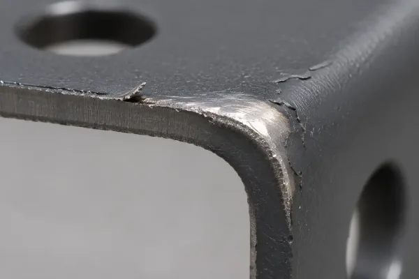
A thin coating film cut by a sharp edge burr and worn through along the sliding path at a bend.
Low Friction Coating Options for Sheet Metal Sliding Surfaces
Four coating families cover most sliding sheet metal applications. Each solves a different part of the problem.
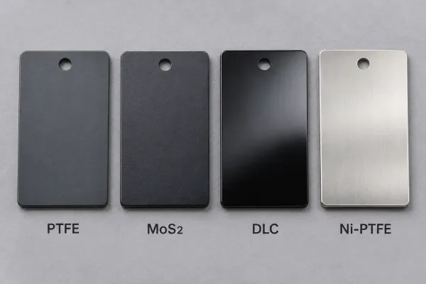
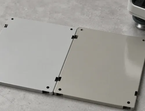
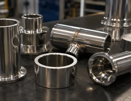
Four steel coupons with different coating finishes: PTFE, MoS₂, DLC, and nickel-PTFE.
PTFE-based coatings
Thermally cured polymer films built on PTFE (polytetrafluoroethylene, a low-friction fluoropolymer), often filled with other solid lubricants. Published COF values run 0.05–0.20 against steel at typical dry film thicknesses of 5–25 µm, with continuous service to about 260 °C (500 °F). The films are soft, so contact pressure must stay moderate; they tolerate chemicals and moisture well and adhere over primed steel and aluminum.
MoS₂ and WS₂ solid lubricant coatings
Sputtered or bonded films of molybdenum disulfide (MoS₂) or tungsten disulfide (WS₂) — solid lubricants that shear easily at the sliding interface. COF in dry or inert conditions drops to 0.02–0.10, the lowest range available. Films are thin (0.5–15 µm). Bonded MoS₂ oxidizes in humid air and loses performance unless it is sealed or run dry or inert; WS₂ holds up better in open air. Both suit oscillating motion, where start-stop friction governs.
DLC coatings
DLC (diamond-like carbon) is an amorphous carbon film, 1–5 µm thick, hardness typically 1,000–3,000 HV, COF 0.05–0.20 dry. It is applied by PVD or CVD (vacuum deposition processes) and usually needs a chromium or silicon interlayer on steel. Cost is the highest of the four families; it earns that cost where wear life dominates and the counterface is smooth and hard.
Plating-based options
Nickel-PTFE is electroless nickel (a uniform autocatalytic plating) with co-deposited PTFE particles: 10–25 µm, COF 0.08–0.15, with corrosion resistance from the nickel matrix — practical for complex sheet metal parts because thickness stays uniform around edges and corners. Hard chrome runs 5–50 µm at about 1,000 HV, COF 0.15–0.25 against steel: tougher, higher friction, and subject to environmental controls on hexavalent chromium processes. For aluminum, PTFE-impregnated hard anodizing (a 25–50 µm anodic layer) is the standard route.
Coating Comparison: The Numbers That Drive Selection
The table condenses typical published ranges. Treat it as a screening tool, not a guarantee, and confirm values with the supplier’s test data on your substrate.
| Coating family | COF (dry, vs steel) | Typical thickness | Max service temp | Contact pressure | Typical substrates | Relative cost |
|---|---|---|---|---|---|---|
| PTFE-based film | 0.05–0.20 | 5–25 µm | ~260 °C | Low | Steel, stainless, aluminum | Low–medium |
| MoS₂ solid film | 0.02–0.10 (dry/inert) | 0.5–15 µm | ~350 °C | Medium | Steel, stainless, titanium | Medium |
| WS₂ solid film | 0.03–0.10 | 0.5–2 µm | ~450 °C (inert) | Medium | Steel, stainless | Medium |
| DLC | 0.05–0.20 | 1–5 µm | ~300–400 °C | High | Steel (interlayer), stainless | High |
| Nickel-PTFE | 0.08–0.15 | 10–25 µm | ~200 °C | Medium–high | Steel, stainless, aluminum | Medium–high |
| Hard chrome | 0.15–0.25 | 5–50 µm | ~400 °C | High | Steel | Medium |
| PTFE-impregnated anodize | 0.10–0.15 | 25–50 µm | ~150 °C | Medium | Aluminum only | Medium |
Read the thickness column as per surface. Two coated sliding faces add twice the film to the clearance — the point where most fit problems start.
How Do You Match a Coating to the Sliding Duty?
Speed and contact pressure
Light panel slides and covers at low pressure take PTFE-based films. Higher contact pressure or wear-critical surfaces move to nickel-PTFE, hard chrome, or DLC. Oscillating motion with direction reversals favors thin solid lubricant films (MoS₂ or WS₂), which hold low static friction and reduce stick-slip.
Environment
MoS₂ in humid open air degrades unless sealed. Washdown or salt exposure points to nickel-PTFE or hard chrome on a corrosion-resistant substrate; PTFE films tolerate chemicals and moisture but not point loading. Above roughly 260 °C, PTFE is out of range; WS₂ and hard chrome extend it.
Mating material and counter-surface
Coat the softer side only — two soft low-friction films against each other usually wear faster than one. Counterface finish matters: a rough counterface cuts thin films, an overly smooth one can stick-slip against them. A hardened counterface around Ra 0.4–0.8 µm suits thin solid films; PTFE tolerates rougher mates.
Life target and maintenance access
If the joint cannot be re-lubricated in service — sealed enclosures, inaccessible rails — bonded solid films and platings outperform grease alone. For very high cycle counts, put the wear-resistant layer (chrome or DLC) on the primary surface and use PTFE only as a secondary aid.
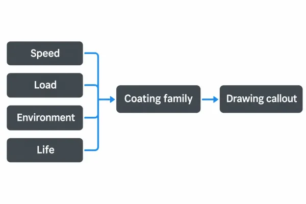
Selection path from sliding duty conditions to coating family to drawing callout.
What Does the Coating Change in Sheet Metal Fabrication?
Film thickness in the tolerance stack
Coating is applied to finished geometry, so every micron lands on the sliding fit. A 10 mm sliding fit with 15–30 µm diametral clearance loses that clearance to 20 µm of film on the shaft side alone. Either design the clearance with coating allowance stated on the drawing, or mask the surfaces that must stay bare — and say which is which.
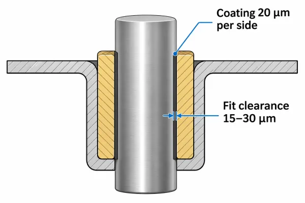
Cross-section of a sliding fit where 20 µm of coating per side consumes the designed clearance.
Forming and bending: coat before or after?
Cured PTFE films crack at tight bend radii. Standard practice is to form first and coat last. If a part must be coated before forming, mask the bend zone; otherwise expect micro-cracking on the inner radius.
Welding and masked areas
Welding after coating burns the film and contaminates the weld pool. PTFE also decomposes above about 260 °C with hazardous fumes. Weld first, then coat; mask seams and heat-affected zones whenever a coated subassembly still sees welding.
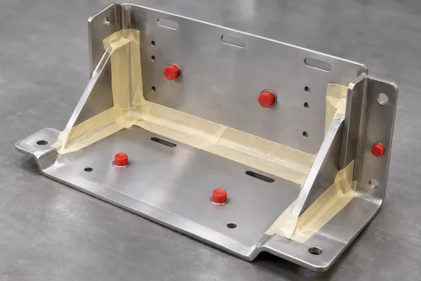
A formed sheet metal bracket with welds and threads masked, ready for the coating step.
Surface prep: burrs, edges, and roughness for adhesion
A burr cuts through a 10–20 µm film under load and starts the wear path. Deburr and break edges before coating. Adhesion needs a blast-cleaned profile (commonly Sa 2½ / SSPC-SP10 near-white metal) and a substrate roughness around Ra 0.8–3.2 µm to anchor the film.
How Should the Coating Appear on Drawings and RFQs?
What a complete coating callout includes
A manufacturable callout states:
- Coating family and reference standard or supplier spec
- Dry film thickness range (e.g., 15–25 µm) per coated surface
- Coated areas (shaded) and masked areas (threads, welds, datum faces)
- Surface preparation standard (e.g., Sa 2½ before coating)
- Inspection method and sampling (thickness by ISO 2178 magnetic induction on steel, eddy current on aluminum; adhesion test if required)
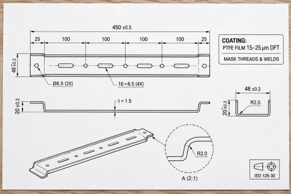
A drawing callout specifying PTFE film thickness and the areas to mask.
Common specification mistakes and what they cost
“Apply low friction coating” with no thickness lets the supplier default — and the fit pays for it. Coated threads lose assemblability. Unmasked datum surfaces create inspection disputes. A COF requirement with no test method is unverifiable at incoming inspection. Each mistake shows up as quotation noise, late engineering changes, or rejected batches.
From Sample to Production: What to Lock Down
Measuring and accepting film thickness
Non-destructive gauges read thickness well when the method is agreed first: magnetic induction over steel for non-magnetic coatings (ISO 2178), eddy current over aluminum. Establish first-article correlation on a cross-section or witness coupon, then write the method and sampling rate into the PO.
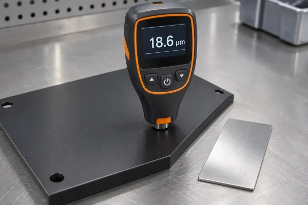
A magnetic induction gauge reading dry film thickness on a coated sheet metal part.
Masking consistency from samples to batches
Hand-taped masks that work on samples become fixture-dependent in production. Define the mask boundary tolerance (±1 mm or a visual limit standard) and keep first-article photos as the acceptance reference for later batches.
Next Step for Your Next RFQ
Define the sliding duty first — speed, load, environment, life — then pick the coating family, state the film thickness in the fit, and agree the inspection method with the fabricator before the order is placed. If you are preparing an RFQ for sliding sheet metal parts, a coating-requirement review at the drawing stage is the cheapest place to close fit and process questions. SR-MFG engineers review coating callouts during DFM as part of RFQ evaluation.